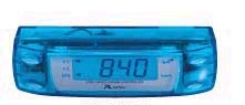
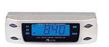
 R Spec VTEC/MIVEC Controller [Type II]
Short Beep = Select/Next
Long Beep = Setting Confirmed
(*place your mouse cursor over the images to understand the readings of the display unit)
 Speed Display: 0-300km/h (+ Disabling of the factory set Speed Limiter)
Press Button II to toggle between SPEED & RPM display mode
Speed Display: 0-300km/h (+ Disabling of the factory set Speed Limiter)
Press Button II to toggle between SPEED & RPM display mode
 RPM Display: Rev Counter
Press Button II to toggle between RPM & SPEED display mode
RPM Display: Rev Counter
Press Button II to toggle between RPM & SPEED display mode
 Dual Memory High Lift Cam Setting (VTEC X-Over Point adjustment)
Press Button I to select. (User Presets: H1 & H2)
Press Arrow Buttons to set
Dual Memory High Lift Cam Setting (VTEC X-Over Point adjustment)
Press Button I to select. (User Presets: H1 & H2)
Press Arrow Buttons to set
 One touch return to (default) factory preset high lift cam setting (VTEC X-Over Point)
Press Button I to select. (H1 - H2 - nor)
One touch return to (default) factory preset high lift cam setting (VTEC X-Over Point)
Press Button I to select. (H1 - H2 - nor)
 Speed Warning Beeper: 10-300km/h
When in SPEED display mode, press the arrow buttons & adjust accordingly
Toggle ON & OFF by pressing both Arrow Buttons Simultaneously (SP:of = Speed Warning function disabled)
Speed Warning Beeper: 10-300km/h
When in SPEED display mode, press the arrow buttons & adjust accordingly
Toggle ON & OFF by pressing both Arrow Buttons Simultaneously (SP:of = Speed Warning function disabled)
 Up-Shift Warning Beeper (Shift Lamp Optional)
When in RPM display mode, press the arrow buttons & adjust accordingly
Toggle ON & OFF by pressing both Arrow Buttons Simultaneously (SU:of = Up-Shift Warning function disabled)
~~~~~~~~~~~~~~~~~~~~~~~~~~~~~~~~~~~~~~~~~~~~~~~~~~~~~~~
Initial Settings (Post Installation):
Note: Prior resetting of ECU is recommended (fuse removal method). I using prefer this method. Engine must be turned off.
Alternatively, you may disconnect the battery's negative terminal before installation.
1) Press & Hold All 4 Buttons Simultaneously to Access Initial settings
2) Press Button II to go to Next & Use Arrow Buttons to Adjust & Set
C-4 = Select the number of Cylinders in your engine. 4, 6 or 8. default setting is 4.
A1.00 = RPM error rate adjustment (%). default setting is 00.
P0.00 = SPEED error rate adjustment (%). default setting is 00.
H-45 = Prevents high lift cam activation below preset speed (km/h). default setting is 45.
cb-of = External Shift Lamp activation. default setting is off.
sb-on = Warning Beeper activation. default setting is on.
3) Press & Hold All 4 Buttons Simultaneously to Exit
4) Finally, install the ECU fuse & start engine ignition.
Start driving to begin calibrating RPM & Speed error rate adjustment (Trial & Error)
~~~~~~~~~~~~~~~~~~~~~~~~~~~~~~~~~~~~~~~~~~~~~~~~~~~~~~~
Up-Shift Warning Beeper (Shift Lamp Optional)
When in RPM display mode, press the arrow buttons & adjust accordingly
Toggle ON & OFF by pressing both Arrow Buttons Simultaneously (SU:of = Up-Shift Warning function disabled)
~~~~~~~~~~~~~~~~~~~~~~~~~~~~~~~~~~~~~~~~~~~~~~~~~~~~~~~
Initial Settings (Post Installation):
Note: Prior resetting of ECU is recommended (fuse removal method). I using prefer this method. Engine must be turned off.
Alternatively, you may disconnect the battery's negative terminal before installation.
1) Press & Hold All 4 Buttons Simultaneously to Access Initial settings
2) Press Button II to go to Next & Use Arrow Buttons to Adjust & Set
C-4 = Select the number of Cylinders in your engine. 4, 6 or 8. default setting is 4.
A1.00 = RPM error rate adjustment (%). default setting is 00.
P0.00 = SPEED error rate adjustment (%). default setting is 00.
H-45 = Prevents high lift cam activation below preset speed (km/h). default setting is 45.
cb-of = External Shift Lamp activation. default setting is off.
sb-on = Warning Beeper activation. default setting is on.
3) Press & Hold All 4 Buttons Simultaneously to Exit
4) Finally, install the ECU fuse & start engine ignition.
Start driving to begin calibrating RPM & Speed error rate adjustment (Trial & Error)
~~~~~~~~~~~~~~~~~~~~~~~~~~~~~~~~~~~~~~~~~~~~~~~~~~~~~~~
 Prevention of high lift cam activation below preset speed (1-99km/h)
Basically, this improves low-speed driveability (for heavily modified engines)
Prevention of high lift cam activation below preset speed (1-99km/h)
Basically, this improves low-speed driveability (for heavily modified engines)
 Rev Counter calibration: ±20%
If the digital reading during RPM display mode does not match with the analog tachometer, use this adjustment for correction
(A1.20 = +20% / A1.80 = -20%)
Rev Counter calibration: ±20%
If the digital reading during RPM display mode does not match with the analog tachometer, use this adjustment for correction
(A1.20 = +20% / A1.80 = -20%)
 Speed Display calibration: ±20%
If the digital reading during Speed display mode does not match with the analog speedometer, use this adjustment for correction
(P0.20 = +20% / P0.80 = -20%)
If you require assistance in adjusting the RPM & Speed Calibration, you may email me as a last resort.
Speed Display calibration: ±20%
If the digital reading during Speed display mode does not match with the analog speedometer, use this adjustment for correction
(P0.20 = +20% / P0.80 = -20%)
If you require assistance in adjusting the RPM & Speed Calibration, you may email me as a last resort.

 Shift Lamps sold separately
Things to keep in mind before installation:
Firstly, If you would like to share your inputs, or have any clarifications... please drop me an email @ spyker_r@yahoo.com
And please do take note (i get alot of emails concerning this request). I do not possess the wiring diagram for the RSVTC.
I certainly would have posted it online if i have one available.
But do not fret, because i recalled the installer had informed me that the wiring formation is pretty similar
to wiring a APEX'i VTEC Controller (eg. Speed & RPM readings, VTEC activation control).
Apparently, the wires are color-coded so i guess it should be a straight forward affair.
Make sure the connection between the wires are tight so as to prevent any leakage or loss of signal.
Symptoms of a bad connection may include:
decreased throttle response, inaccurate readings, failure of functions, etc.
Obviously, do not make any connection if the color of the wire from the Module does not match the color of the wire from the ECU.
Just simply isolated the bare wire from the Module & leave it alone.
There will be definitely be one or more unused wire(s) from the Module depending on the engine's ECU.
Heat shrink tubings are the best for making a decent connection.
Trust me, just by using those sticky, gooey, messy electrical adhesive tape is really not advisable!
Commendable installers/mechanics always use Heat shrink tubings.
Taking the effort of Soldering the connections prior to the usage of Heat shrink tubings would be the most ideal & secure.
Inform your installer/mechanic to do so if you must.
Professional installation should cost about 30 to 40 bucks & completion duration in about 30 minutes...
And of course, preferbly done by someone whom has experience in installing APEX'i VTEC Controllers.
With some effort & ingenuity, i believe an inexpensive customized harness could be created too.
I also declare that I shall not be held responsible if you did not get the Module installed by a professional
before experiencing any type of mishap(s) to the ECU &/or engine caused by the RSVTC.
DIY'ing is a good thing but doing it in a correct manner is most imperative.
Return to Function Manual Download page
~~~~~~~~~~~~~~~~~~~~~~~~~~~~~~~~~~~~~~~~~~~~~~~~~~~~~~~
Specifications
(Heat Resistant ABS)
Control Unit:
Size = W86mm × H24mm × D23mm
Weight = 30g
Display = LCD + EL Blue Back Light
Main Unit:
Size = W83mm × H28mm × D88mm
Weight = 60g
~~~~~~~~~~~~~~~~~~~~~~~~~~~~~~~~~~~~~~~~~~~~~~~~~~~~~~~
A somewhat important brief note on the RSVTC (for Honda VTEC) & the RSMVC (for Mitsubishi MIVEC):
If you did not make any major modifications on the engine, there are no reasons to connect
the wire to control the VTEC or MIVEC crossover point.
Even if it's connected, i would advise against changing the crossover point.
The factory set crossover point has already been optimized,
hence controlling the crossover point will seriously affect the performance of the engine.
However, the RSVTC or RSMVC is a great multi-function tool.
Evidently, the most attractive function of this device is the Soft Speed Limiter Over-ride...
which is great for JDM machines that comes standard with a Soft Speed Limiter which activates @ approximately 180km/h.
Including the Soft Speed Limiter Over-ride & the other great functions offered by this device...
(display unit, shift-up warning, speed warning & etc) not only makes it relatively inexpensive,
(compared to the HKS Speed Cut Limit Defencer or the GREDDY Speed Cut Controller that has only a single purpose)...
the RSVTC (with a compact Main Unit) is a pretty versatile tool for your JDM ride & it has a good resale value.
Lastly, as far as i know...
the RSVTC Type II can only be exclusively coupled onto B, C, D, F & H series Honda engine ECU's
(with or without VTEC) like the EG/EK Civic, DC2 Integra, BA/BB Prelude.
But for Mitsubishi... Unfortunately, I have no knowledge or info on that. My Apologies.
(Email me if you have any info as this will benefit other RSMVC owners too).